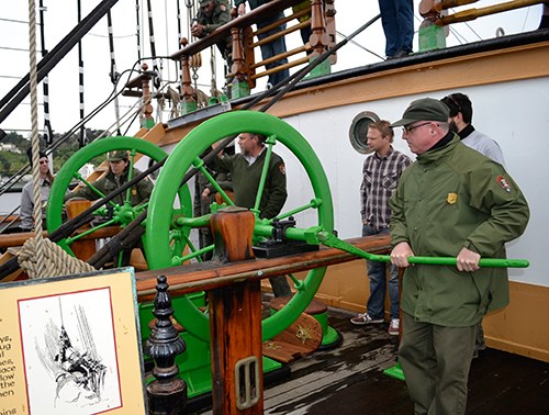
NPS Photo The Ship's Maintenance crew have reconditioned, renewed, and replumbed the starboard side pump to pump water, in order to show visitors how the crew in the working days of the ship got out any water that leaked into the hull. Notes From Ship’s Bilge Pumps; A History of their Development 1500-1900 (Thomas J. Oertling) By Courtney Andersen, Former Historical Ship Rigging Supervisor April 9, 2014 Pumps were the last defense, hope, and salvation of the lives on board. A ship could lose its rig or its rudder, and still give a hope of survival, but without a working bilge pump a ship was lost. The 18th century naval architect William Hutchinson observed that crews sometimes left ships too soon; that the ship may appear in imminent danger of foundering but was discovered hours or days later to be still afloat. After the water rises high enough to cover a leak, the rate of inflow is reduced; equilibrium is reached, and the ship often won’t go down much further, making it possible for the crew to pump and plug the leak. With usually one or two “heads” aboard a ship, and sometimes hundreds of sailors, many sailors used the bilge as a latrine. The accumulation of filth and garbage in the hold polluted the bilges, and though a health hazard, the nature of the bilge water provided proof of whether the hull was tight: Boteler 1634: “when it stinketh much, it is a sign that the water hath lain long in the hold of the ship; and on the contrary, when it is clear and sweet, it is a token that it comes freshly in from the sea. This stinking water therefore is always a welcome perfume to an old seaman; and he that stops his nose at it is laughed at, and held but a fresh-water man at best.” There were basically only three types of ship bilge pump used from the 1400s to the 1800s: --burr pumps: basically, a cone-shaped leather bucket that drew water up a tube --chain pumps: a continuous chain with small burrs or buckets to catch water and pull it up, running over upper and lower sprockets --common or “suction” pump: the earliest representation is from 1431. Use on ships was probably from sometime in late 1400s to early 1500s. The first recorded use of metal parts in ship pumps was 1526. Usually, they were made entirely of wood until the late 1700s because the only tools available for boring iron tubes were those to make cannon. In 1712, the first practical steam engine was invented by Newcomen. A steam engine needed the piston and cylinder in very tight tolerances. Initially made by hand, ground and filed…further developments in boring machines were needed before steam could progress, and it wasn’t until those machines were made that all-metal pumps could be manufactured. Dodgson’s Patent Ship Pump 1799—similar to the pump on Balclutha, but still a common suction pump, using up-and-down pump handles to drive two pump boxes with two valves in each box. Most of the early suction pumps rely on a moving upper one-way valve attached to a rod, and a stationary lower valve with a “claque” or one-way flap that allows water to move past it. The pump must be primed when there is no column of water in the tube. Water must cover the upper valve, sealing off the lower part of the tube from the air. As the piston works, the atmospheric pressure decreases in the tube. The water then rises through the lower valve because of the greater atmospheric pressure outside the tube pushing the water into the tube. The height to which a common pump can raise water by suction is governed by barometric pressure -- about 28’ from surface of the water to the “claque” of the upper valve at the top of the stroke. It wasn’t until the 1850s that the iron flywheel to help maintain momentum of rotation was developed to work with a camshaft to drive the two piston rods. This quickly became the standard on packets and clipper ships. Balclutha’s pump by Robert Mills of Greenock, Scotland is an improved “force pump” design which uses a central water-filled piston chamber connected to two valve chambers. Each of these valve chambers has two heavy valves with leather gaskets. Water is drawn up past the lower valve by the piston’s suction stroke; the lower valve then seals closed; then when the piston pushes against the water in the pump case, it is pushed past the upper valve and out through the discharge “dale.” The two sets of valves means that the pump ejects water smoothly in both the up and the down motions of the piston; this is known as “double action.” This “force pump” design was known to the Romans, but it wasn’t until metal working progressed in the mid-1800s that it became a practical shipboard pump style. A force pump differs from a common suction pump in that the valves are not located on the piston rod. 

NPS Archives 

NPS Photo |
Last updated: October 5, 2024
